Blocks Warning: This guide has excessive use of blocks.
Welcome to my latest (and first in a long time) GKC guide!
In this guide, I’ll be going through the six basic logic gates in electronics and coding, and explaining how to create each of them with block code in Gimkit Creative to compare two true/false properties.
Table of contents:
- Intro
- Table of contents
- How these explanations will work
- AND gate
- OR gate
- XOR gate
- NAND gate
- NOR gate
- XNOR gate
- Conclusion
How these explanations will work
Okay, so, basically, for each gate, we’ll have three true/false properties: Input 1, Input 2, and Output. I’ll explain how to create the gate with block code, comparing the two input properties to determine the output (which, if you didn’t know, is what a logic gate does).
Now, with two inputs which can each be in two different states, there are four possible combinations the gate can recieve:
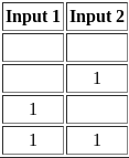
But there are only two possible outputs, so depending on the gate, the number of possible ways the output can be 1 versus the number of possible ways it can be 0 can vary.
For each gate, I’ll give an explanation of what the gate does, I’ll show a table with the four possible input combinations, and the output that would come out of each, and I’ll then show the block code to make the gate, with a brief explanation of exactly what it does.
Anyways, let’s get started!
Important note: If I say that an input’s value is 1, or its value is true or it is set to true, or it is powered, those all mean the same thing.
AND gate
An AND gate checks if both inputs have a value of 1, or true, then the output becomes 1 as well. Therefore, as shown below, only one input combination can power the output of the gate.
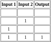
The block code for this one is quite simple, here it is:
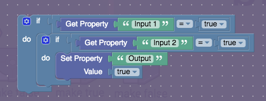
Basically, it checks if the first input is powered/true, and if it isn’t, it does nothing else, but if it does, it checks if the second input is also powered. If it isn’t, once again, the script is over, but if it is, then it powers the output.
OR gate
An OR gate is pretty simple: it checks if at least one input is powered. If this is true, it powers the output. The only combination that does not power it is if neither input is powered.
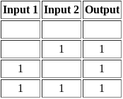
The block code for it is also pretty simple:

Basically, it checks if the first input is powered, and if it is, it powers the output, finishing the script. If it is not powered, it checks if the second input is, and if it is, it powers the output and finishes the script. If it isn’t, it just finishes.
XOR gate
The XOR gate works similarly to the OR gate, but unlike the OR gate, if both inputs are powered, it does not power the output. One, and only one, input must be powered.
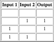
Surprisingly, the block code for this one is actually quite simple:

It checks if the two inputs are the same. They could be both true or both false. If either of these are true, it does nothing. If they are not true, it means the two inputs are different, so only one is powered, therefore, the output is powered.
NAND gate
The NAND gate powers the output if less than two of the inputs are powered. As its name sort of states, the NAND gate’s output is powered when the AND gate’s output is not, and vice versa.
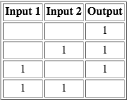
Once again, not too complicated to make in block code:
It works by checking if both inputs are powered, and if they are, it does nothing, but if they are not both powered (so, if one or neither of them are), it powers the output.
NOR gate
The NOR gate is basically an OR gate with an inverted output signal. If neither input is powered, the output is. Where an OR gate’s output would be powered, a NOR gate’s output isn’t, and vice versa.
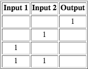
The NOR gate’s block code is sort of similar to the NAND gate:
It checks that both inputs are false, and if this is the case, it powers the output.
XNOR gate
And now, the final logic gate of this guide, the XNOR gate.
The XNOR gate, sort of similarly to the NOR gate, checks if the inputs are the same, as in, if they are both powered or both not powered, and if either of these is true, its output is powered.
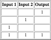
Despite its complicated-sounding name, the XNOR gate is actually one of the simpler and easier gates to create using block code:

It simply checks if both inputs are the same, and if they are, powers the output.
Conclusion
So there you go! The six basic logic gates, made in Gimkit Creative block code!
Yes, I know there’s also a NOT gate, but I’m only doing the ones with two inputs.
Complex operations can be performed using combinations of these logic gates. In theory, there is no limit other than memory to the number of gates that can be arrayed together in a single contraption - or a single device - a single block, for that matter. Arrays of logic gates are found in digital ICs (integrated circuits). As IC technology advances, the required physical volume for each individual logic gate decreases and digital devices of the same or smaller size become capable of performing ever-more-complicated operations at ever-increasing speeds. I suppose that probably isn’t really true for Gimkit though lol
Thanks for reading this guide, I hope you learned something, and I hope this helps you and/or improves your Gimkit Creative experience! ![]()
Resources:
https://www.techtarget.com/whatis/definition/logic-gate-AND-OR-XOR-NOT-NAND-NOR-and-XNOR

