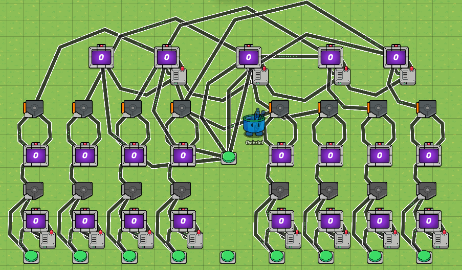
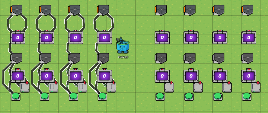
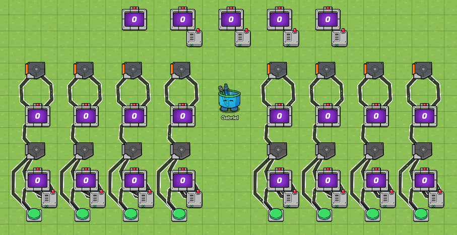
This is a VERY basic design, as I just made this, so it can only add numbers together. The only binary digits the answer has are 16, 8, 4, 2, and 1; while the input numbers only have up to 8. But this is easier in the sense that the main columns for each input digit is essentially just the same thing copied. Would recommend having Grid Snap set to 64; Go to the bottom-left settings, enter editing options, scroll down until you see grid snap.
Here is an image of it when it is NOT condensed:
Pretty intimidating, huh?
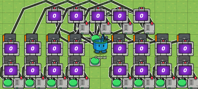
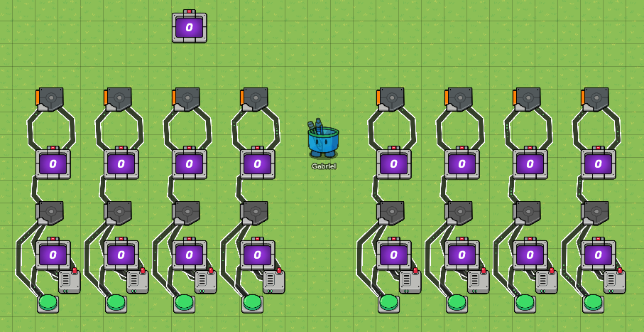
But here is a picture of it when it is condensed:
Lists of devices needed:
- 10 Buttons
- 21 Counters
- 16 Triggers
- 12 Wire Repeaters
- 89 Wires
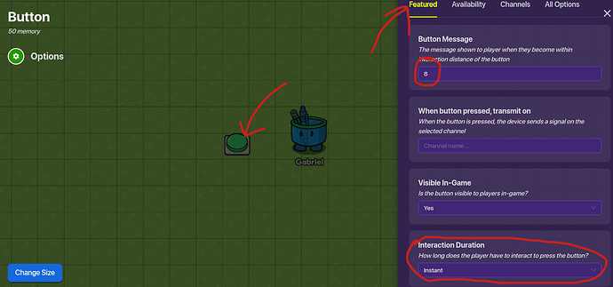
Step 1: For step 1, let’s start to build just one column, and then we can copy all of them and change it where we need to. Start with a simple button, and in its “Featured” options, change the message to “8”, and change the Interaction Duration to “Instant”.
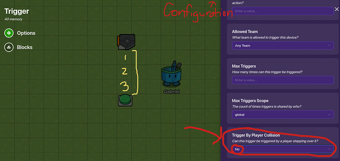
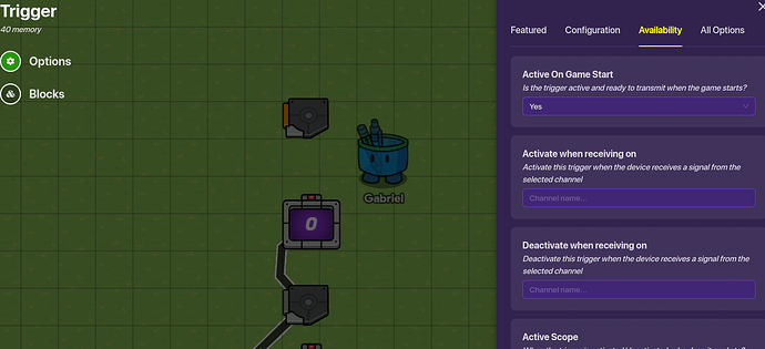
Step 2: Get a trigger and put it around 4 blocks above the button (3 blocks in between). Go into the trigger options, go to configuration, and set “Trigger By Player Collision” to “No”. After that, go into “Availability” and switch “Active On Game Start” to No. Then, go into “Featured” and put “Solve” into the “Trigger when receiving on” section.
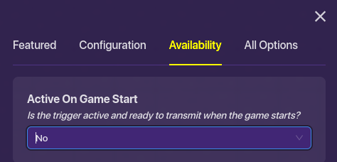
Step 3: After you have done this, connect a wire from the button to the trigger, and apply the following conditions:
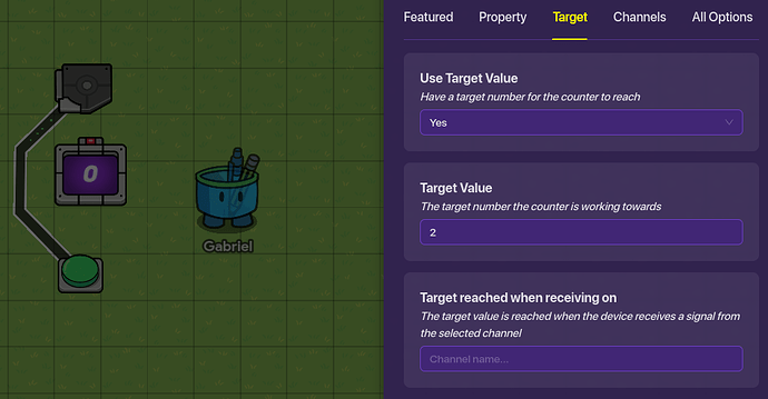
Step 4: get a counter from Devices and put in the middle of the button and trigger. Go into “Target”, select “yes”, and set the target value to 2.
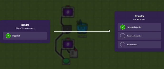
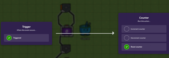
Step 5: Place a wire repeater to the bottom right of the counter. Now connect a wire from the button to the counter with these conditions:
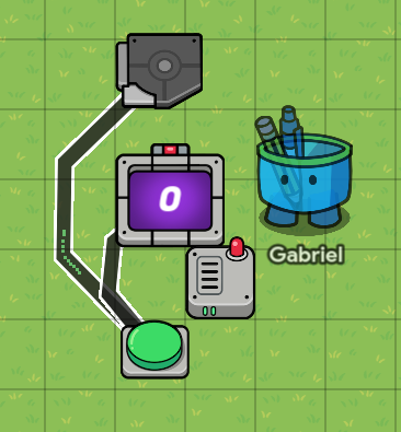
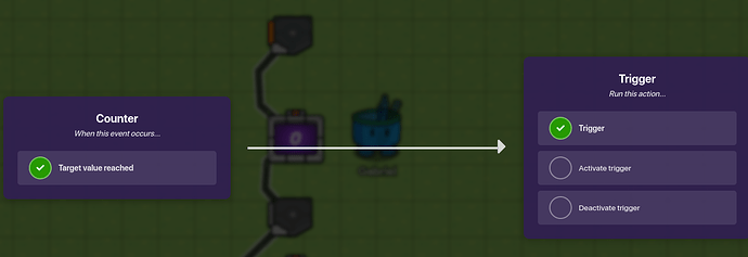
Step 7: Connect the counter to the wire repeater via wire with the conditions “Target Value Reached” for the counter. Then connect the wire repeater back to the counter via wire with the conditions “Reset Counter”. Finally, place a wire from the wire repeater to the trigger saying “When the wire repeater receives a pulse → deactivate trigger”.
^^^(This was added after step 11)^^^
Step 8: Copy the first counter and place it 2 blocks above the trigger, but change the target value to 1 instead of 2. Connect the trigger and 2nd counter with a wire that says “Triggered → Increment Counter”.
Step 9: Copy the first trigger and place it 2 blocks above the 2nd counter, but change the availability to be active when the game starts.
Now connect a wire from the 2nd counter to the 2nd trigger with these conditions (A), and loop it back to the counter with the conditions (B):
(A)
(B)
By now, going from the top to the bottom, the devices should be: Trigger, Counter, Trigger, Counter, Wire Repeater, Button.
Step 10: Copy this entire column by clicking and dragging your mouse across the entire thing, and put the next ones like so:
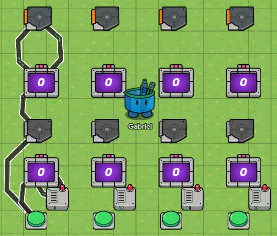
Step 11: Connect each of the devices in the copied columns with wires with the same conditions that you have done for the first column. Make sure to rename the buttons, so from left to right, the messages for the buttons should be: “8 4 2 1”.
Step 12: Copy the entirety of the 4 columns and place the large copy 5 blocks away (4 blocks in between) from the wire repeater on the farthest right; again, don’t forget to place wires in the places that you have been doing for the first 4 columns.
Step 13: Copy one of the BOTTOM row counters (The ones with the target value of 2) and place it 3 blocks above the 2nd to far right, top-row trigger on the left set of columns (What a mouthful!)
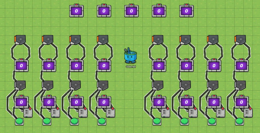
Step 14: Copy that top counter 4 more times and put each one in a row so that they are 1 row apart, but not touching/overlapping.
Step 15: Copy one of the wire repeaters and place it to the bottom-right of the 2nd counter on the top (So skip one, the first one is for the 16 spot.) Then copy it for the other three in the same spot for each counter.
Then connect the counter to the wire repeater and loop it back, similar to the way you did it in step 7.
Wire diagram (Expanded)
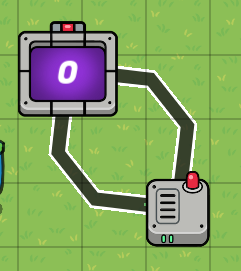
Step 16: Do that with each of the top counters that have the wire repeater. Now, connect a wire from the wire repeater for the far right counter (1’s spot) to the 2’s spot counter; do that same thing for the 2’s spot and 4’s spot, and down the line until you stop at the 16’s spot.
Wire conditions for the wires that connect to the wire repeater to the NEXT counter (2’s repeater to 4’s counter, and so on).
Step 17: Connect wires from the top triggers of the left set of columns to their respective counters at the top (8’s spot trigger connects to 8’s spot counter, etc.) Each with the condition “Triggered → Increment Counter”.
Step 18: Connect wires from the top triggers of the RIGHT set of columns to their respective counters at the top, each with the conditions “Triggered → Increment Counter”.
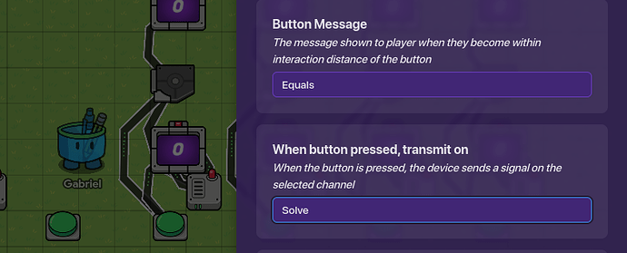
Step 19: Copy any button and put it somewhere in the middle of the 2 sets of columns, but in the same row as the rest of the buttons. Change the message to say “Equals” or “Solve” it doesn’t really matter. But put the “Solve” Channel where it says “When button pressed, transmit on”.
This will allow all of the bottom row triggers to activate, which will then solve the equation.
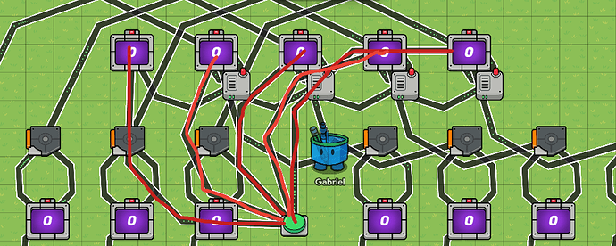
Finally, Step 20: Copy that button and put it in the middle within the row of the middle row counters, like in the first image of this guide. Change the name to “Reset” and clear the channel broadcast that said “Solve”; connect wires from that button to each of the top counters, with the conditions “Button Pressed → Reset counter”.
Red lines show the wires that are connected to the reset button.
That’s it! You can choose different numbers (Currently up to 15!) for the 2 inputs, hit solve, then it should show you the answer in binary! from the left to the right, the digits for the top counters go “16 8 4 2 1”. I hope you have enjoyed this guide, and I am looking for ways that I might be able to improve this design with! Thank you and bye!
