I need help on how I can make my Basic Binary Calculator (BBC or BC, I’ve dubbed) be able to do subtraction. It can do addition, but I’ve been stuck on how to do subtraction. It’s not just reversing it to where if the trigger is activated, then DECREASE the counters, because that would interfere with the binary aspect a bit. I have an idea, it may be good for now, but idk about later, and it’s going to be maybe hard to explain but bare with me.
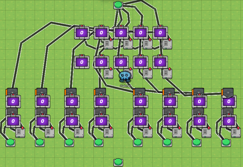
My Idea: So based on the picture below, the finished row of counters on the very top is the addition row, while the row below it is subtraction. My idea is that instead of trying to make the machine choose and change the way it works for the different operations (Division, Multiplication, addition and subtraction), what if it did them all to begin with?
The basic idea is the the calculator will compute the equation for every operation separately, but put barriers over the rows that hide all but one row- the operation that you chose. Here’s an example:
We say 15 for first number and 7 for second number, and we set it to addition; it shows 22 on top row of counters, and 8 on the row below it; there’s a barrier that’s connected to the operation buttons, and since you pressed addition, the addition barrier hides, while the subtraction barrier stays shown…
That might be confusing, idk, but it’s probably the easiest solution that will cause less roadblocks to appear. I’m looking for help, though; help with my idea, and looking for other possible ideas.
REMINDER: I’m trying to make this work without properties or block code, so try to think of ideas that don’t involve those things…
But even if we connected wires to the top triggers to the subtraction row, how are we going to make it cancel out the numbers, WAIT… I’ve thought of something…
What if, instead of trying to figure out how to make both numbers into one with subtraction, we just put one number first, then subtract the second number from it in pieces? Like if the equation was 6-4, we would put 6 (00110), then have the 4 column in the second number area then subtract the 1 in the 4 counter of the finished number? It would go from 00110 as the finished number, to changing the number by the second input, 00100, so it’ll just change that 4 counter in the output- 00010? It’s really hard to explain, if you couldn’t tell lol
Subtraction is actually just the same as adding- just invert one of the numbers, so all the 1’s become 0’s and the 0’s become 1’s, and add 1. Then add the numbers. For example:
7 - 3
111 - 011
Invert:
011 → 100
Add one:
100 → 101
Add:
101 + 111 = 1100.
Cut:
Cut out the first digit of the answer:
1100 → 100
I’ve been trying to come up with ideas that will make it work, and so far i’ve come up with this:
The wires that originally connected the top most triggers to the output counters are now connected to a new set of triggers, these ones will be activated/deactivated with the plus and minus operation buttons. Those triggers will be connected to wire repeaters just so you can have multiple wires coming from it. These wire repeaters will be connected to the digit to the left of the digit that the focused column is (Ex: for the 4 column, the wire repeater will be connected to the 8 output counter). That wire will tell the digit counter (DC) on the left to be reset; then the wire repeater it’s connected to will be connected to another repeater with a delay until after that digit has done it’s work, then be connected to the proper digit counter (4 column to 4 DC). Basically, it’s telling the DC on the left of the target counter (TC) to reset, then tell the TC AFTER it’s been reset by the next wire repeater, because it’s done subtracting, it just needs to put in the resulting numbers. EX: 1st number is 8, 1000, the 2nd number is 4, 0100. The second number column tells the 8 output counter to reset, 00000, then ad 1 to Target Counter (TC), 0100. I know that’s super complicated, but it IS hard to explain…
Though this idea may work, I’ve just made the XOR, OR, and NOT gates, so I might test the gates out, though I’m kinda confused on what the inputs should be connected to.