Before you view this guide, it is recommended that you build my last guide, if you are interested in building this one. This is going to be similar to the first guide in the first few steps, but it’s going to get a whole lot different. Also, it is best to have grid snap to 64 for this because I can say “Place this 4 blocks away, etc.”
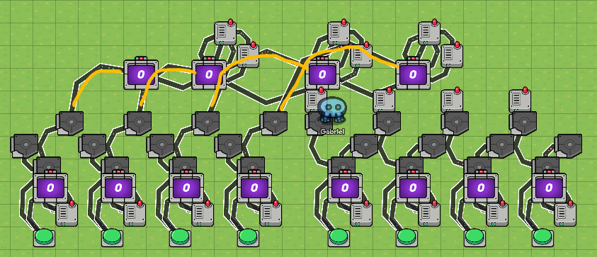
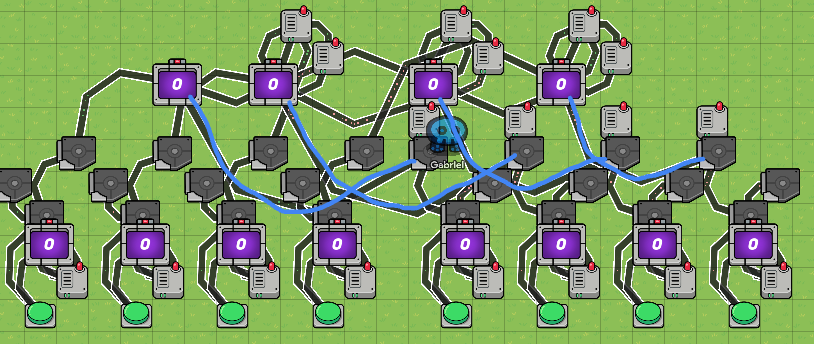
Since you have looked at or followed along to that guide, get ready to change it into this all-new calculator! vvv
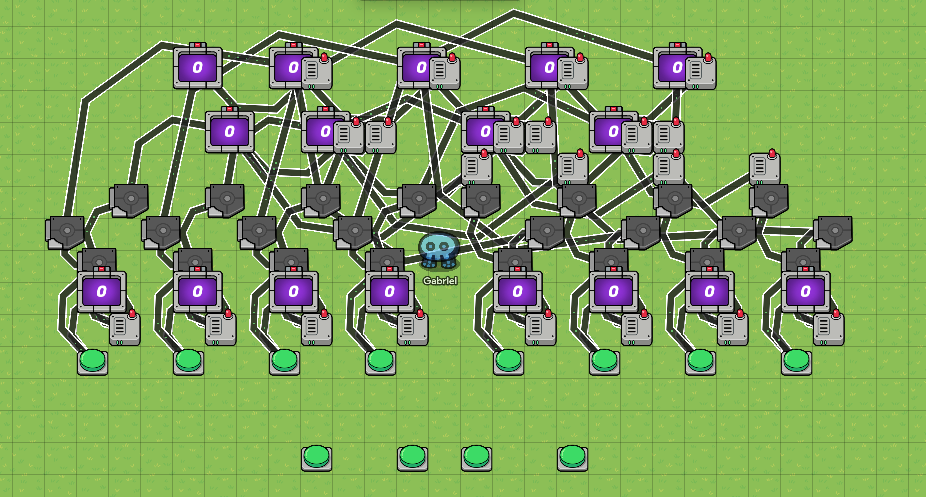
I know it seems like a lot because- honestly it kind of is- but it is pretty much a BUNCH of copy/pasting devices. Here is a list of the materials needed for this new guide:
- 24 triggers (3 kinds of UNIQUE triggers, though)
- 12 buttons
- 17 counters
- 22 wire repeaters ( 10 of these have a 0.1 second delay)
- 103 wires (POV: You when you see “103 wires”

 )
)
I’m going to be splitting this guide into 5 sections: Beginning Row; Trigger Central; Subtraction Row; Addition Row; and Operational Buttons.
Beginning Row:
- 8 triggers
- 8 counters
- 8 wire repeaters
- 8 buttons
- 40 wires
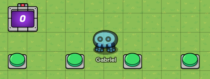
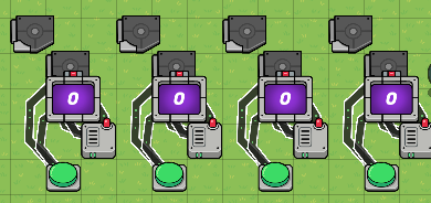
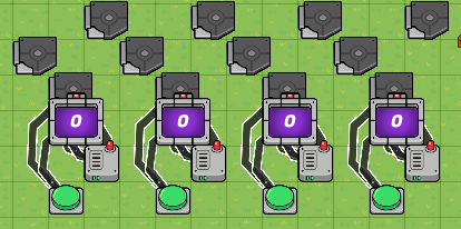
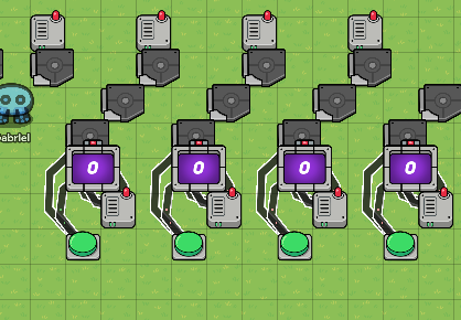
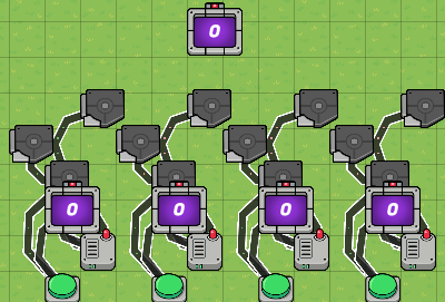
Step 1: place 4 buttons in a row, with the Interaction Duration set to “Instant”. Place each one 3 blocks away from the next (2 blocks in between).
Step 2: Label the buttons, from left to right, “8” then “4” then “2” then “1”.

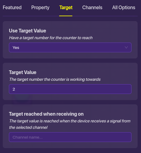
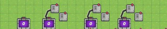
Step 3: Place a counter 2 blocks above the left-most button (1 block in between). Set the starting value to 0, and select “yes” for a target number in the target tab in the counter. Set the target number to 2.
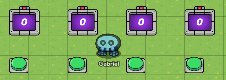
Step 4: Copy that counter and place it 2 blocks above every other button, like the first.
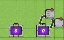
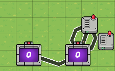
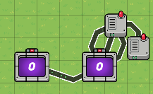
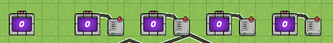
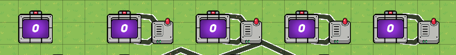
Step 5: Place a wire repeater on the bottom right of each counter (Top right of the buttons), 4 in total, without changing the delay on any of them.
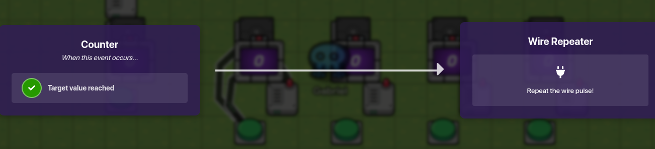
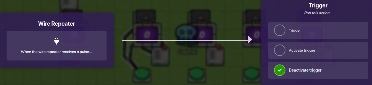
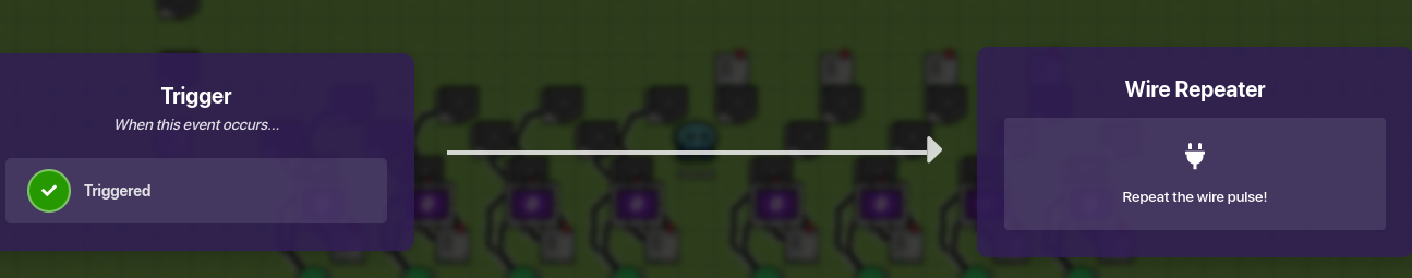
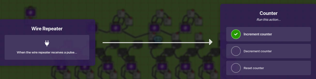
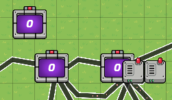
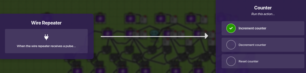
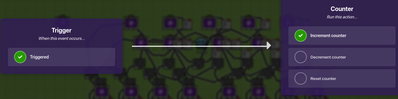
Step 6: Place a trigger directly above each counter, 4 in total, in the same line with the button. Configure the trigger like the images below:
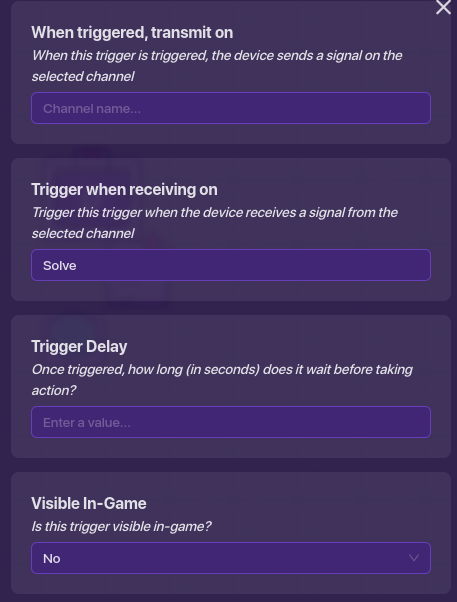

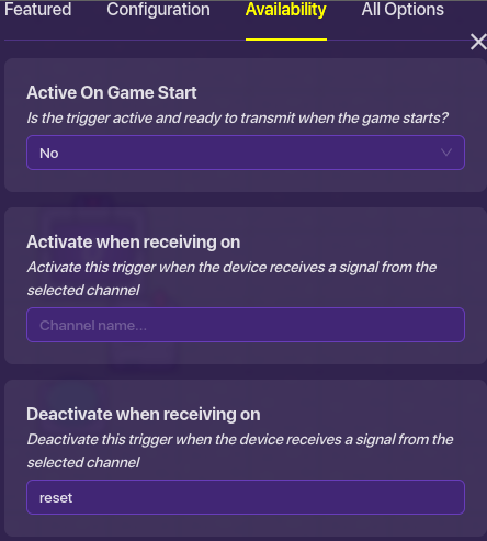
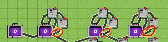
Step 7: Copy that trigger to the rest of the columns, each one directly above the counters, it should look symmetrical when you are done.
Step 8: Wire each device in the first column like the sub-steps below:
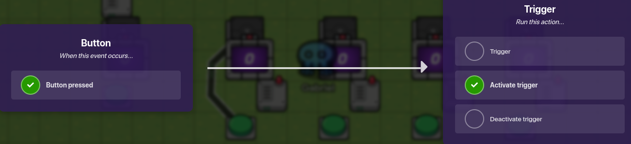
- Wire the button to the trigger, with the conditions of press button-> activate trigger (A).
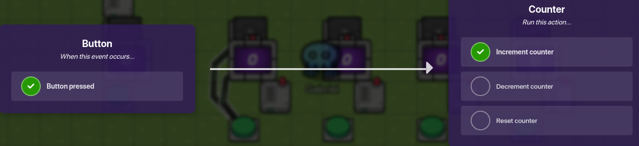
- Wire the button to the counter with the conditions of press button-> increment counter (B).
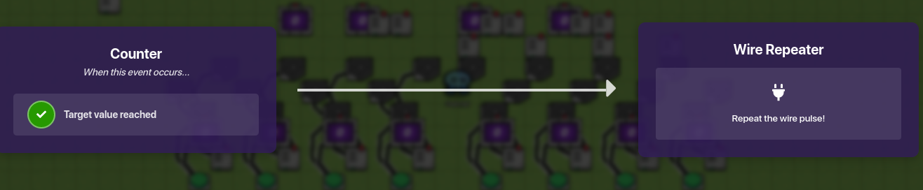
- Wire the counter to the wire repeater with the condition that the target value is reached (C).
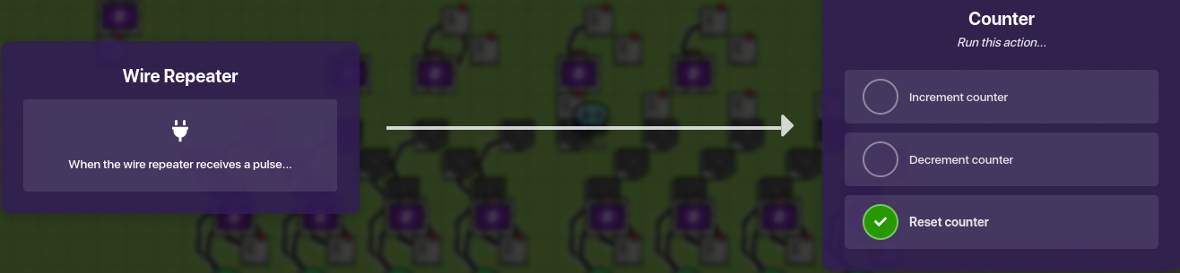
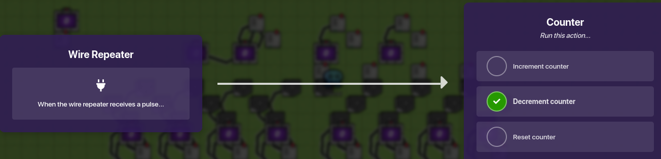
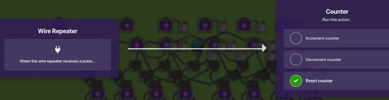
- Wire the wire repeater back to the counter with the condition that it resets the counter (D).
- Wire the wire repeater to the trigger with the condition that it deactivates the trigger (E).
(A)
(B)
(C)
(D)

(E)
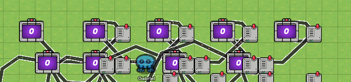
Step 9: Repeat that process for every column, so it will be 20 wires in total.
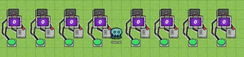
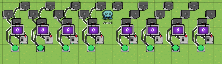
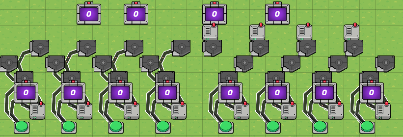
Step 10: Copy the entire 4 columns and place it so that the right-most button of the ORIGINAL set of columns is 4 blocks away from the COPIED set (3 blocks in between).
Trigger Central:
- 16 triggers
- 20 wires
- 4 wire repeaters
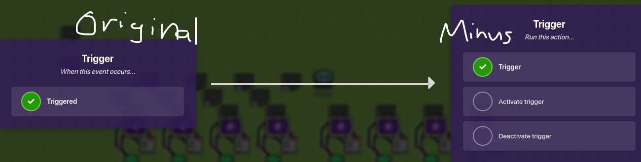
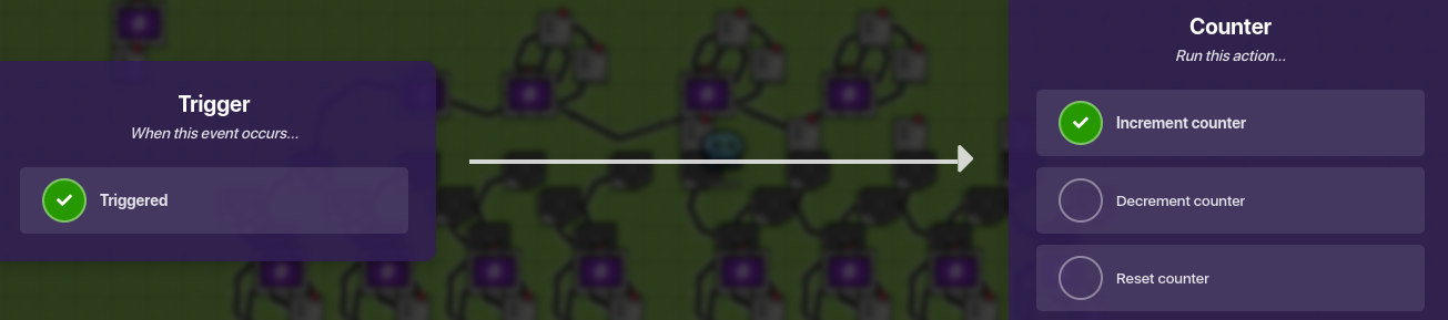
Step 1: Copy one of the triggers in the last section, but clear the channel “Solve” in “trigger when receiving on”. This will be the “Plus” trigger. Then, configure the trigger like the images below:


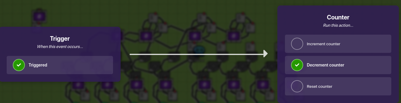
Step 2: Copy the plus trigger and switch the activate and deactivate channels, so it activates on “Minus” and deactivates on “Plus”. This will be the “Minus” Trigger.
Step 3: On the left set of columns, place plus triggers to the top left of every original trigger on each column (A); place the minus triggers 1 block above and 2 blocks to the right of the plus triggers (B).
(A)
(B)
Step 4: Wire the original trigger to both the plus and minus triggers, each with the condition that triggered->trigger.

Step 5: On the Right set of columns, place the plus triggers on the top RIGHT of the original triggers, then place the minus trigger 1 block above and 2 blocks to the LEFT of the plus triggers, mirroring the left set.
Step 6: Place wire repeaters- with a 0.1 second delay- above the minus triggers on the right set, with 4 in total.
Step 7: Wire the Original triggers to the Plus triggers, and the original triggers to the minus triggers the same way done on the left set (triggered->trigger).
Step 8: Wire the minus triggers to the wire repeaters above them with the condition of triggered->repeat wire pulse.
Subtraction Row:
- 4 counters- Set the target number to -1
- 6 wire repeaters with a 0.1 second delay
- 15 wires
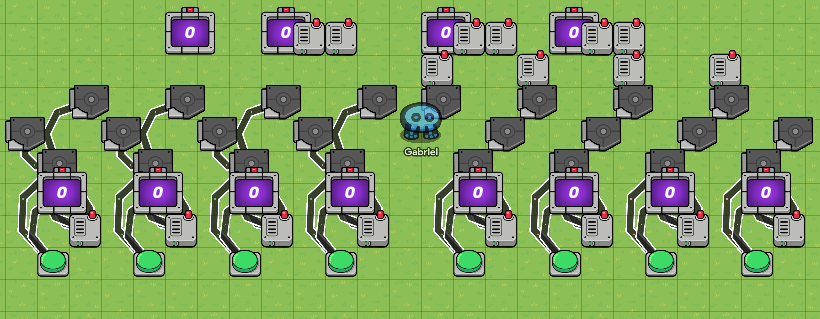
Step 1: Place a counter 2 blocks above (1 block inbetween) the 2nd minus trigger on trigger central, starting from the left.
Step 2: Place another counter 3 blocks to the right of the first one.
Step 3: Place another counter 5 blocks to the right of the last one you placed.
Step 5: Place a counter 4 blocks to the right of the last counter.
Step 6: Place wire repeaters immediately to the right of the 3 right-most counters, then place another one next to it.
Step 7: Wire every counter to the wire repeater that they are touching (immediately to the right) with the condition that the target value is reached.
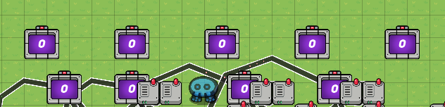
vvv Wire repeaters moved to show wires vvv
Step 8: Wire the wire repeaters 1. Back to the counter to reset counter (A); 2. To the counter to the left of it’s connected counter (B); 3. To the second wire repeater (C)
(A)
(B)
(C)
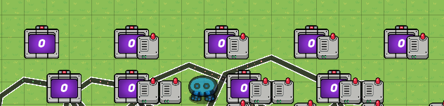
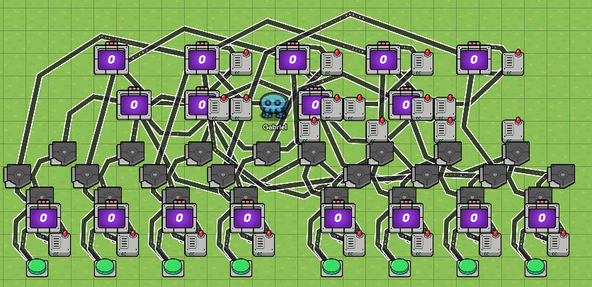
When you are finished, it should look something like this:

Step 9: Wire the second wire repeater in each series to the connected counter with the condition that it increments the counter.
Step 10: 1. Going back to Trigger Central, on the left set, wire all the MINUS triggers to the counters, with their numbers respectively.
- On the right set now, wire all the wire repeaters (the ones that are connected to the minus triggers) to the counters, numbers respected.
Addition Row:
- 5 counters- set the target to 2
- 4 wire repeaters- set the delay to 0.0 seconds
- 17 wires
This is the same thing as the resulting number row in the first guide that was linked at the top, so you can go there and look at it, but here’s a run-down of it really fast:
- Place a counter 2 blocks above and 1 block to the left of the left most counter in subtraction row. Copy that counter 4 blocks to the right of the original one, do that until you have 5 counters in total.
- Place wire repeaters immediately next to the 4 right-most counters, without any delay.
- Wire those counters to the wire repeaters saying “Target value reached”; wire the repeaters BACK to the counters saying “Reset counter”; also wire the repeaters to the counter on the left off the connected counter saying “increment counter”.
- Wire all the PLUS triggers to the aaddition row, with respect to the numbers of the columns.

Sorry, that might have been a little confusing, but I’ve been working on this guide since yesterday, and I’m starting to lose patience lol. If you have any questions, feel free to ask, and I will try my best to answer them. Hope you enjoyed this guide, and I always like suggestions on what to do next!
