Previous Parts
Making a 16-bit Computer in Gimkit! (Chapter 1: CPU, Part 2: Logic Gates)
Making a 16-bit Computer in Gimkit! (Chapter 1: CPU; Part 1: Instruction Set and CPU)
Making a 4-Bit Computer in GKC
Chapter 1: CPU, Part 3: Registers and Beginning the ALU
I made a mistake last guide...
In the last guide, I made a very massive mistake: I overlooked that logic gates could be expressed using only arithmetic operations (addition, subtraction, multiplication, and division). Here are the updated versions of each logic gate without using conditionals but rather math.
AND
Q = A × B
OR
Q = A + B - A × B
NOT
Q = 1 - A
NAND
Q = 1 - ( A × B )
NOR
Q = 1 - ( A + B - A × B)
XOR
Q = A + B - 2 × A × B
XAND
Q = 1 - ( A + B - 2 × A × B )
Intro
In this guide, we will be making registers and beginning designing the ALU, or the part that does math (addition, subtraction, multiplication, and division).
Registers
Registers hold data. Since this is a 4-bit computer, each register will hold a 4-digit long binary numbers (ex. 1001 which is 9). In GKC, registers can be made using properties. For now, we can make just 10 registers, but this number can be upgraded. I will name the properties “register 1-10”.

Keep the Property Type as Text because in the ALU, I will need to separate data values into individual bits, or digits, to be processed one by one. Keeping it as text lets me easily separate the digits while also being easy to convert to a number (multiply the text by 1). Now, one major issue here is if I wanted to convert the text value “0001” (which is 1 in decimal) into a number, it will output “1” instead of “0001”. The reason why this is bad is because when I single out each digit in 0001 and 1, the digits are different. The first digit in 0001 is 0, while the first in 1 is 1. This throws off arithmetic calculations. A simple fix to this append a different number that doesn’t show up in binary to the start of the data. You can use any number from 2-9, but I will use 2. This can be easily accounted for later when coding the ALU. Now change the default value of all the properties to “20000”.
The ALU
The ALU, as I explained in part 1, is a major component in the CPU that does arithmetic operations. The ALU takes 4 inputs and uses those 4 to output 2 outputs. The 4 inputs are as follows:
- Opocode
- Operand 1
- Operand 2
- Status In
The 2 outputs are as follows: - Result
- Status Out
The opocode tells the ALU what arithmetic operation to do (ADD, SUB, DIVI, MULT). The 2 operands are the 2 numbers the ALU is operating on. The status in is the status out from the previous operation. Status out is if something special happened in the math (carry, overflow, zero, signed). Carry means that there was a carry or borrow in the addition or subtraction, respectively. Overflow means that the signed binary number was too large to express in 4 bits. Zero means the output was 0, and signed means the number could possibly be negative. More about signed and unsigned numbers will be in the next part you will have to wait rehehehehe
How does the computer turn the opocode into arithmetic operations?
The opocode is always a number from 0-3 (00 = ADD, 01 = SUB, 10 = DIVI, 11 = MULT), but how does the ALU know which one it is which? They do this using a **decoder**, specifically a 2-4 decoder, meaning it takes a 2-bit binary input and outputs 4 distinct outputs. Here would be a truth table for the 2-4 decoder we want to design:| A | B | Y0 (ADD) | Y1 (SUB) | Y2 (DIV) | Y3 (MUL) |
|---|---|---|---|---|---|
| 0 | 0 | 1 | 0 | 0 | 0 |
| 0 | 1 | 0 | 1 | 0 | 0 |
| 1 | 0 | 0 | 0 | 1 | 0 |
| 1 | 1 | 0 | 0 | 0 | 1 |
We can look at the relationships between A, B, and an output. First, we can start with the relationship between A, B, and Y0. We can see the relationship is a NOR gate. The next easiest relationship to see is A, B, and Y3. This relationship is an AND gate. Now, Y1 and Y2 are harder because they aren’t symmetrical (symmetrical meaning the output stays the same with any permutation of the inputs). Since they are asymmetrical, one of the inputs will go through a NOT gate while the other stays non-inverted. After some trial and error, the circuits for Y1 and Y2 are as follows:
Y1 = ¬A · B (¬ means NOT and · means AND)
Y2 = A · ¬B
Here are the circuits for decoder in block code:
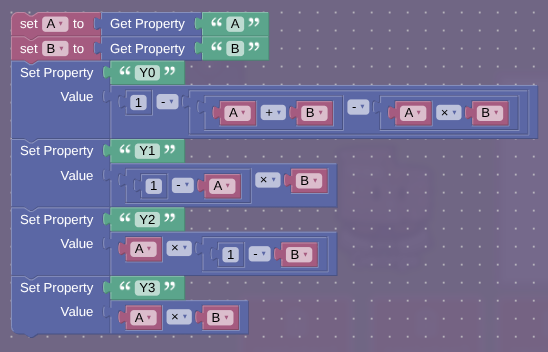
Ask questions I will answer them for like 1-2 hours after posting